はじめに
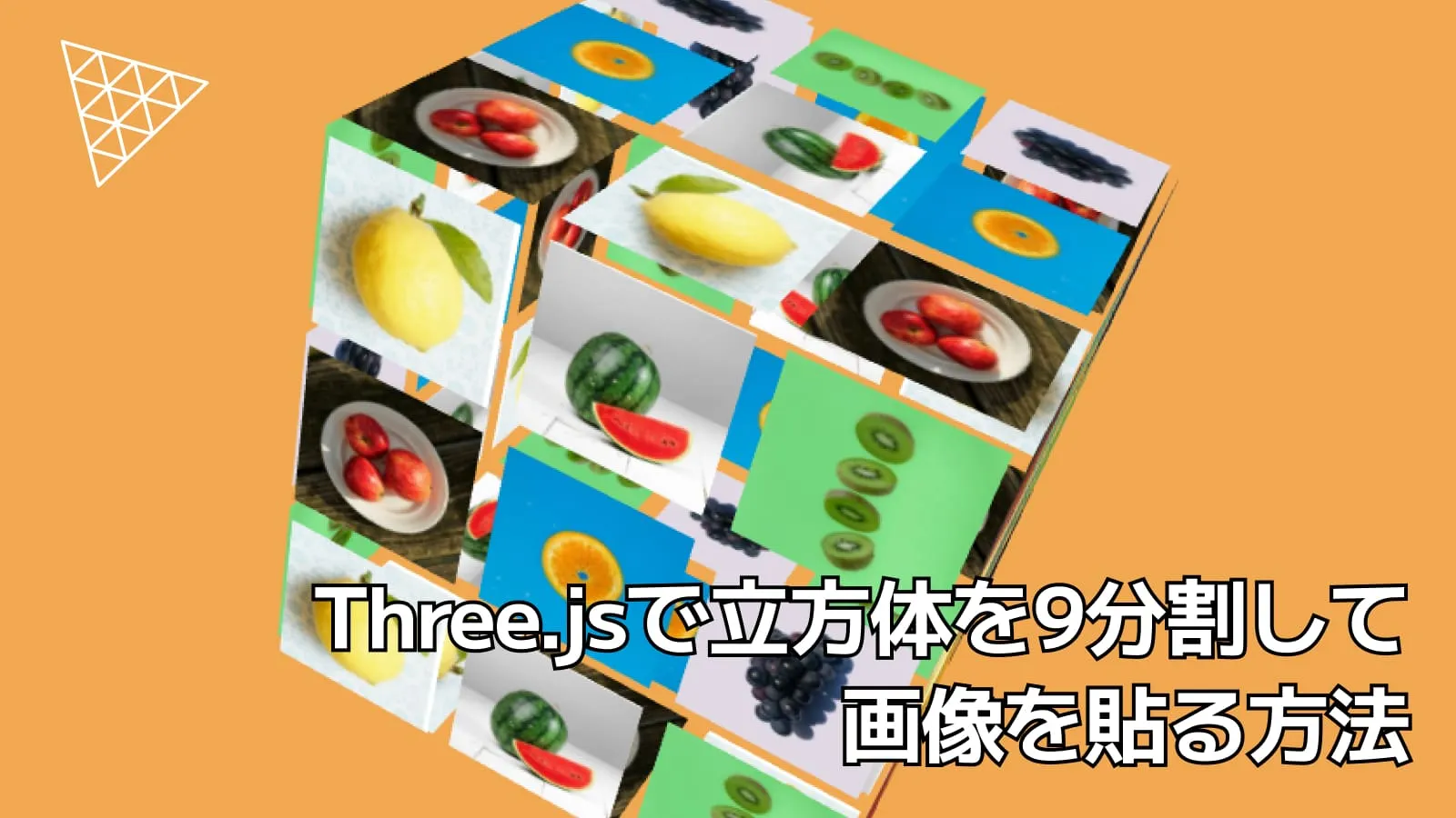
Three.jsのPlaneGeometryを9x6=54個使用して立方体を作り、画像を貼るやつ
— かめのの (@kameno_no3) April 25, 2026
reference sitehttps://t.co/q3EvTetOKi#threejs #webgl #glsl pic.twitter.com/akk6tLV7d3
こちらのサイトのトップページのように、立方体の各面を9分割した面に画像を貼る方法を紹介します。またテキストをホバーしたら、シェーダー側の操作で該当する画像のみを表示する方法も解説します。
Three.jsの開発環境は以前の記事を参考にしてください。
この記事のデモのコードは以下のGitHubリポジトリにあるので、ぜひ参考にしてください。
実装の考え方
Three.jsで立方体を作成する方法として、BoxGeometryを使用する方法がありますが、今回は立方体の各面を9分割して画像を貼るために、PlaneGeometryを面の数分(9x6個)作成し、座標変換して立方体を作成する方法を採用します。
また、Three.jsのInstancedMeshを使用することで、同じジオメトリとマテリアルを1回のドローコールで描画することで効率化を図るようにします。
画像は、各面ごとに異なる画像が貼られるようにします。このデモでは、6枚の画像をuTextureとして配列でシェーダーに渡し、App.tsのaTexIndex属性でどの画像を表示するかをシェーダー側で制御しています。
イントロのアニメーションとテキストホバーでの立方体を拡大させるアニメーションに関してはGSAPを使用します。
それでは、PlaneGeometryを54個作成して、立方体を作成する方法を解説します。
立方体の作成
立方体の定義
立方体は、6面から構成されており、各面は9分割されているので次のように変数で定義しておきます。
private readonly divisions = 3; // 1面の分割数
private readonly faceCount = 6; // 立方体の面の数
private readonly totalCount =
this.divisions * this.divisions * this.faceCount; // 全タイルの数 = 3 * 3 * 6 = 54
private readonly cubeSize = 1.2; // 立方体のサイズ
private readonly gap = 0.05; // タイル間の隙間また、ここでは立方体のサイズをcubeSize、タイル間の隙間をgapと定義しています。
立方体の面の定義
PlaneGeometryで立方体を作成するために、各面の方向を次のように定義します。
ここでは、3次元でrightをx軸、upをy軸、normalをz軸とします。
type FaceConfig = {
right: [number, number, number];
up: [number, number, number];
normal: [number, number, number];
};
private readonly faceConfigs: FaceConfig[] = [
// front
{
right: [1, 0, 0],
up: [0, 1, 0],
normal: [0, 0, 1],
},
// back
{
right: [-1, 0, 0],
up: [0, 1, 0],
normal: [0, 0, -1],
},
// right
{
right: [0, 0, -1],
up: [0, 1, 0],
normal: [1, 0, 0],
},
// left
{
right: [0, 0, 1],
up: [0, 1, 0],
normal: [-1, 0, 0],
},
// top
{
right: [1, 0, 0],
up: [0, 0, -1],
normal: [0, 1, 0],
},
// bottom
{
right: [1, 0, 0],
up: [0, 0, 1],
normal: [0, -1, 0],
},
];frontの正面は分かりやすいと思いますが、backの背面で考えると、frontを裏返しにしていると考え、rightとnormalが-1になっています。その他の面も同様に考えれば理解できるかと思います。
createGeometry
createGeometryメソッドで、PlaneGeometryでのジオメトリの作成と、ShaderMaterialでのマテリアル、InstancedMeshでのメッシュの作成を行います。
private createGeometry() {
const cell = this.cubeSize / this.divisions;
const geometry = new THREE.PlaneGeometry(
cell - this.gap,
cell - this.gap,
);
const material = new THREE.ShaderMaterial({
vertexShader: vertex,
fragmentShader: fragment,
side: THREE.DoubleSide,
uniforms: {
uTextures: { value: this.textures },
uActiveTex: { value: -1 },
uProgress: { value: 0 },
}
});
this.mesh = new THREE.InstancedMesh(geometry, material, this.totalCount);
this.setInstanceMatrices(cell);
this.setTextureIndices();
this.scene.add(this.mesh);
}cellは、1面の分割されたタイルのサイズを計算しています。例えば、立方体のサイズが1.2で、分割数が3の場合、1枚のタイルのサイズの範囲は0.4になり、gapで定義した隙間を引いた値をPlaneGeometryの引数に指定することで、タイル間に隙間ができるようにしています。
uniformsには、シェーダーに渡すテクスチャの配列と、ホバーしたときに表示するテクスチャのインデックス、イントロのアニメーションの進行度を渡しています。
このgeometryとmaterialと全タイルの数(totalCount)をInstancedMeshに渡すことで1回のドローコールで済ませることができます。
setInstanceMatricesメソッドは、各タイルを立方体の面に配置するための座標変換を行います。setTextureIndicesメソッドは、各タイルにどの画像を使うかを設定します。
setInstanceMatrices
Three.jsのObject3DとVector3を使用して、各タイルの位置と回転を計算して、InstancedMeshのインスタンス行列に設定します。
private setInstanceMatrices(cell: number) {
const dummy = new THREE.Object3D();
const baseNormal = new THREE.Vector3(0, 0, 1);
let index = 0;
this.faceConfigs.forEach((face) => {
const right = new THREE.Vector3(...face.right);
const up = new THREE.Vector3(...face.up);
const normal = new THREE.Vector3(...face.normal);
for (let y = 0; y < this.divisions; y++) {
for (let x = 0; x < this.divisions; x++) {
const px = (x - 1) * cell;
const py = (1 - y) * cell;
const position = new THREE.Vector3()
.addScaledVector(right, px)
.addScaledVector(up, py)
.addScaledVector(normal, this.cubeSize / 2);
dummy.position.copy(position);
dummy.quaternion.setFromUnitVectors(baseNormal, normal);
dummy.updateMatrix();
this.mesh.setMatrixAt(index, dummy.matrix);
index++;
}
}
})
}pxとpyの箇所は、各タイルの中心位置を計算しています。例えば、分割数が3の場合、pxは-0.4, 0, 0.4の値をとり、pyは0.4, 0, -0.4の値をとります。
ここで具体的にbackの面の場合を考えると、rightは[-1, 0, 0]、upは[0, 1, 0]、normalは[0, 0, -1]になります。例えば、左上のタイルの場合(x=0, y=0)、pxは-0.4、pyは0.4になるので、位置は次のように計算されます。
const position = new THREE.Vector3()
.addScaledVector(right, px) // [-1, 0, 0] * -0.4 = [0.4, 0, 0]
.addScaledVector(up, py) // [0, 1, 0] * 0.4 = [0, 0.4, 0]
.addScaledVector(normal, this.cubeSize / 2); // [0, 0, -1] * (1.2 / 2) = [0, 0, -0.6]結果として、位置は[0.4, 0.4, -0.6]になります。これは、正面からみて右上の位置になります。奥側の方向に向くように裏返しにしたいのですが、backのnormalは[0, 0, -1]になるので、baseNormalの[0, 0, 1]とsetFromUnitVectorsを使用することで、Z+ -> Z-となり裏返しになります。
このように計算した行列をInstancedMeshのsetMatrixAtメソッドでindexと一緒に設定することで、各タイルが立方体の面に配置されます。
setTextureIndices
setTextureIndicesメソッドでは、各タイルにどの画像を使うかを設定します。
private setTextureIndices() {
const texIndices = new Float32Array(this.totalCount);
for (let i = 0; i < this.totalCount; i++) {
texIndices[i] = i % this.faceCount;
}
this.mesh.geometry.setAttribute(
'aTexIndex',
new THREE.InstancedBufferAttribute(texIndices, 1)
);
}テクスチャのインデックスをaTexIndexという属性に設定し、シェーダー側でどの画像を使用するかを決めます。
なので、vertexシェーダーでは次のようにしておきます。
attribute float aTexIndex;
varying float vTexIndex;
void main() {
vTexIndex = aTexIndex;
}fragmentシェーダーでは次のようになります。
varying float vTexIndex;
uniform sampler2D uTextures[6];
vec4 getTex(int id, vec2 uv) {
if (id == 0) return texture2D(uTextures[0], uv);
if (id == 1) return texture2D(uTextures[1], uv);
if (id == 2) return texture2D(uTextures[2], uv);
if (id == 3) return texture2D(uTextures[3], uv);
if (id == 4) return texture2D(uTextures[4], uv);
return texture2D(uTextures[5], uv);
}
void main() {
vec2 uv = vUv;
int id = int(vTexIndex);
vec4 base = getTex(id, uv);
gl_FragColor = base;
}ここまでで、立方体の各面に9分割されたタイルに画像が貼られるようになりました!

テキストホバーで該当の画像だけを表示する
最後に、テキストをホバーしたときに、シェーダー側の操作で該当する画像のみを表示する方法を解説します。
準備としてHTML側を次のようにします。
<ul class="links">
<li><a href="" data-slug="apple">Apple</a></li>
<li><a href="" data-slug="orange">Orange</a></li>
<li><a href="" data-slug="grape">Grape</a></li>
<li><a href="" data-slug="remon">Remon</a></li>
<li><a href="" data-slug="watermelon">Watermelon</a></li>
<li><a href="" data-slug="kiwi">Kiwi</a></li>
</ul>識別するために、data-slug属性を使用します。
次にApp.tsで画像の管理のための変数を定義します。
type FruitKey =
| 'apple'
| 'orange'
| 'grape'
| 'remon'
| 'watermelon'
| 'kiwi';
export class App extends Three {
// ...
private readonly textureMap: Record<FruitKey, number> = {
apple: 0,
orange: 1,
grape: 2,
remon: 3,
watermelon: 4,
kiwi: 5,
};
}ホバーイベントについては次のようになります。
private setupHoverEvent() {
const links = document.querySelectorAll('.links a');
const material = this.mesh.material as THREE.ShaderMaterial;
links.forEach(link => {
link.addEventListener('mouseenter', () => {
const slug = link.getAttribute('data-slug') as FruitKey;
const next = this.textureMap[slug];
this.handleHoverEvent(material, next);
});
link.addEventListener('mouseleave', () => {
this.handleHoverLeave(material);
});
});
}
private handleHoverEvent(
material: THREE.ShaderMaterial,
next: number
) {
this.activeTex = next;
this.progressTween?.kill();
material.uniforms.uActiveTex!.value = this.activeTex;
this.progressTween = gsap.to(material.uniforms.uProgress!, {
value: 1,
duration: 0.45,
ease: 'power2.out',
});
gsap.to(this.mesh.scale, {
x: 1.25, y: 1.25, z: 1.25,
duration: 0.45,
ease: 'power2.out',
});
}
private handleHoverLeave(material: THREE.ShaderMaterial) {
this.progressTween?.kill();
gsap.to(material.uniforms.uProgress!, {
value: 0,
duration: 0.45,
ease: 'power2.out',
});
gsap.to(this.mesh.scale, {
x: 1, y: 1, z: 1,
duration: 0.45,
ease: 'power2.out',
});
}uActiveTexにホバーしたときのテクスチャのインデックスを渡し、uProgressでアニメーションの進行度を渡しています。また、ホバーしたときに立方体を拡大させるアニメーションも追加しています。
fragmentシェーダーは次のように追加します。
uniform float uActiveTex;
uniform float uProgress;
void main() {
// ...
float isActive = step(0.1, 1.0 - abs(vTexIndex - uActiveTex));
// 非アクティブ側の強さ(progressに応じて強まる)
float dim = (1.0 - isActive) * uProgress;
// 黒を被せる(0.0〜0.8くらいで調整)
float overlayStrength = 0.85 * dim;
vec3 color = mix(base.rgb, vec3(0.0), overlayStrength);
// 透明度も少し落とす(0.4〜0.8くらいで調整)
float alpha = mix(base.a, base.a * 0.4, dim);
gl_FragColor = vec4(color, alpha);
}isActiveは、ホバーしているテクスチャと同じテクスチャかどうかを判定しています。step関数を使用して、vTexIndexとuActiveTexの差が0.1以上であれば非アクティブとみなしています。
該当以外の画像に関しては、非表示にするのではなく薄く黒を被せるようにしました!

これで完成です!
長くなるので、イントロアニメーションについてはGitHubのコードを参考にしてください。
まとめ
Three.jsで立方体を9分割して画像を貼る方法を解説しました。PlaneGeometryを9x6個作成し、座標変換して立方体を作成し、画像をマッピングする方法を紹介しました。また、テキストホバーで該当する画像のみを表示する方法も解説しました。